Communicating directly between two ESP8266 NodeMCU’s via UART
Overview
In this tutorial, we are going to be focussing on communication between two ESP8266 NodeMCU's — but not in the way most people connect these boards. Instead of wireless communication between modules, we are going to have them communicate via a wired connection using the UART protocol. It is natural to want to use their built-in WiFi capabilities to communicate, but there are some advantages to doing so with UART instead.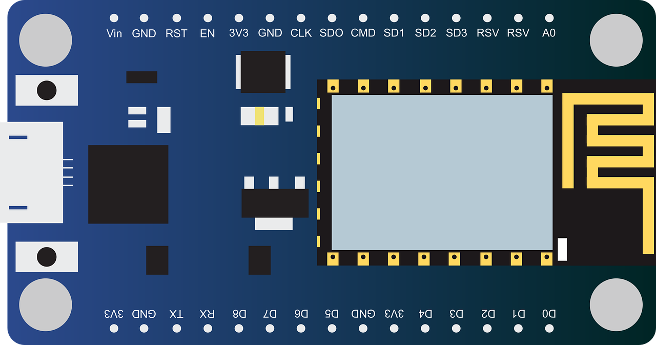
For starters, you may not want to transmit all data between devices over WiFi. You may want each board to use its WiFi capabilities for a specific purpose like hitting an API, while you isolate the inter-board communication to a wired connection. It’s also possible that you may want to communicate between one of these boards and a non WiFi enabled device. For example, you can use an ESP8266 to communicate with a Game Boy Advance via UART to effectively give the handheld wireless and internet capabilities (Video: Connecting a GBA to the Internet and Downloading HTML/CSS). To keep things simple, we'll just stick to using two ESP8266's for today.
Specifically, we'll be using the ESP8266 NodeMCU 1.0 (ESP-12E Module). Let's jump in!
Basic Setup
What You'll Need:
We’ll have one sender and one receiver ESP8266 NodeMCU. You can pick these up on Amazon and other websites very easily. I personally got mine on Amazon from here. I'm going to assume that you know how to flash these boards using the Arduino IDE. Because sender and receiver are both ESP8266's and run on 3.3V, no resistors are required here. We'll power both devices through their Micro USB ports using USB to Micro USB cables.
You'll connect the receiver ESP8266 to your dev computer's USB port which will power it and allow you to read it's received messages in the Serial Monitor of the Arduino IDE. If you have multiple USB ports on your dev computer, then you can power the sender ESP8266 the same way. Otherwise, you can use a USB hub or seperate power source for the sender. Personally, I like to use USB hubs that can be independently powered and have individual on/off switches for each port like this one.
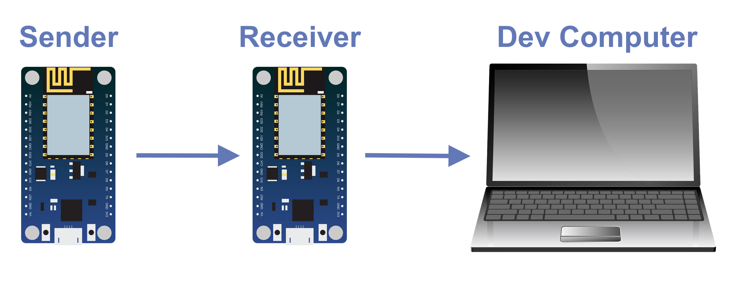
We'll be using the Arduino IDE to write the code, flash the boards, and to use it's built in Serial Monitor to watch for messages from the receiver ESP8266. The sender will have a message that the receiver doesn't know. It will periodically send that message to the receiver via UART. Once the receiver gets the message, it will then send that message to the dev computer so that it can be read in the Serial Monitor of the Arduino IDE. If the Serial Monitor displays the correct message that originated from the sender, then we know the UART communication between the sender ESP8266 and receiver ESP8266 was successful.
Actually the message the receiver sends to the dev computer is sent using the UART protocol as well, but these development boards have a built in UART to USB converter. The message ends up being converted before it is sent over the Micro USB to USB cable and subsequently read by the Serial Monitor in the Arduino IDE on the dev computer.
UART Communication
In it’s simplest form UART Communication really just requires 3 wires (assuming the devices are independently powered). There are the Tx and Rx lines (transmitter and receiver) and the GND (ground) line. And that’s it. Pulses are send over Tx and Rx representing 1’s and 0’s, and the two devices have a common ground. Each chunk of data sent with UART communication includes a start bit, a series of data bits, and 1 or 2 stop bits.
Importantly, the Tx line for one device is connected to the Rx line of the other and vice versa. This may be a little strange if you are used to working with electronics and expect like pins to connect together (like GND to GND) but makes sense when you think about communication. The Transmitter of A connects to Receiver of B and Transmitter of B connects to Receiver of A. For more details on the UART protocol see this article. Other than that, the two devices must transmit and receive data at the same speed. This is the “baud rate” we’ll be setting and must be the same for both devices. There is more to be learned about UART communication and I encourage you to search around after completing this tutorial, but for our purposes that should cover the basics.
First let’s open up the Arduino IDE and load up our two ESP8266 NodeMCU’s with the sender and receiver programs respectively. Then we’ll wire them together and test the setup.
Sender Code
Open up a new file/project in the Arduino IDE. I’m going to assume you have the Arduino IDE installed already or can install it yourself. Make sure to set the board to “NodeMCU 1.0 (ESP-12E Module)” in Tools > Board.
Enter the following code into your new file:
/* SENDER ESP8266 */#define LED D0void setup() {// Set baud rate, switch Rx/Tx pins to D7/D8Serial.begin(115200);Serial.swap();pinMode(LED, OUTPUT);}int i;void loop() {// Create msg, and send using UART over Rx/Tx (D7/D8)String toPrint = "Hi ESP #2! " + String(i);Serial.println(toPrint);delay(500);digitalWrite(LED, LOW);delay(500);digitalWrite(LED, HIGH);i++;}
A line to pay attention to here is line 8 where it says Serial.swap(). This is needed because the NodeMCU dev board is set up with a UART to USB converter connected to it’s Micro USB port which interferes with the default Tx/Rx pins. When we call Serial.swap(), it swaps the Rx pin to D7, and the Tx pin to D8 (both shifted two over). These are the actual pins we’ll be using for Rx and Tx. Other than that, we’ve set the baud rate to 115200 which we’ll need to do on the receiver ESP8266 as well. The LED related code is just to blink the onboard LED to let us know when it sends the message "Hi ESP #2! " + String(i) via UART. The iterator variable i increases by one on each send, so you can see that it is the i-th message sent. As you can see it will send the message with the current value of i, then delay, then update i and repeat.
Flash one of your two ESP8266 NodeMCU's with the code above. This is now your Sender ESP8266
Receiver Code
The receiver module will listen for any messages over UART and then relay them to your dev computer for you to verify in the Serial Monitor of the Arduino IDE.
Create another new file/project in the Arduino IDE and enter the following code:
/* RECEIVER ESP8266 */// Create data buffer for messages up to 40 characterschar msgBuffer [40];volatile byte indx;// Set baud and switch Rx/Tx to D7/D8void setup() {Serial.begin(115200);Serial.swap();}void loop() {// Listen for received UART data on Rx/Tx (D7/D8)if (Serial.available() > 0) {byte currentByte = Serial.read();if (indx < sizeof msgBuffer) {msgBuffer [indx++] = currentByte;// If end of message, send to dev computerif (currentByte == '\r') {String message = String(msgBuffer);Serial.swap();delay(200);Serial.println(message);delay(200);Serial.swap();delay(200);indx = 0;}}}}
As you can see we set the baud rate to 115200 and switch Rx/Tx to D7/D8 on this board as well.
In the loop, we listen for incoming UART data, and if we receive any then we relay it over to your dev computer. When we do this, notice that we call Serial.swap() twice. This is to switch UART communication back to the default Rx/Tx pins which will actually be sent through the Micro USB port to our computer. Then we switch back to D7/D8 again so that we'll be able to receive the next message from the sender ESP8266. It can take a moment for the swap to finalize so we use delays to ensure sending and receiving data on the correct pins.
Now flash your second ESP8266 NodeMCU with the receiver code above. This is now your Receiver ESP8266
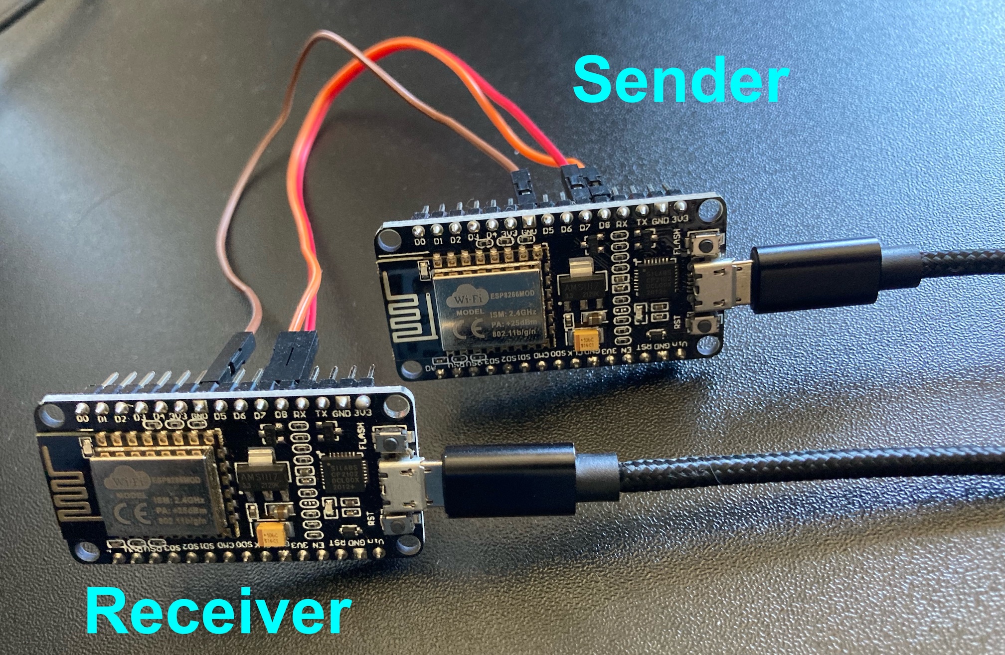
Wiring Sender and Receiver
Start with both NodeMCUs off and unplugged. Neither should be connected to a power source yet. Wire the two boards together with the following instructions.
Connect D7 of sender to D8 of receiver
Connect D8 of sender to D7 of receiver
Connect GND of sender to GND of receiver (I would use GND next to D5)
Insert USB to Micro USB cables into the Micro USB ports of both devices, leaving the USB ends disconnected. You will plug in the USB ends in the next step to run the setup.
Running the Setup
Connect the receiver to your dev computer with a USB to Micro USB cable. This is so that you can open the Serial Monitor in the Arduino IDE (it may not let you if it's not plugged in). Go to Tools > Serial Monitor to open it. Once opened, disconnect the the cable from the USB port while leaving the Serial Monitor opened. You will plug it back in, but only after the sender is on and sending messages.
Now power on your sender ESP8266 with another USB to Micro USB cable connected to a seperate power source. With the LED of the sender blinking (indicating that it is sending messages via UART), plug the receiver back into the USB port of your dev computer.
The Serial Monitor in the Arduino IDE should now be printing "Hi ESP #2! <number>" with an increasing number once every second: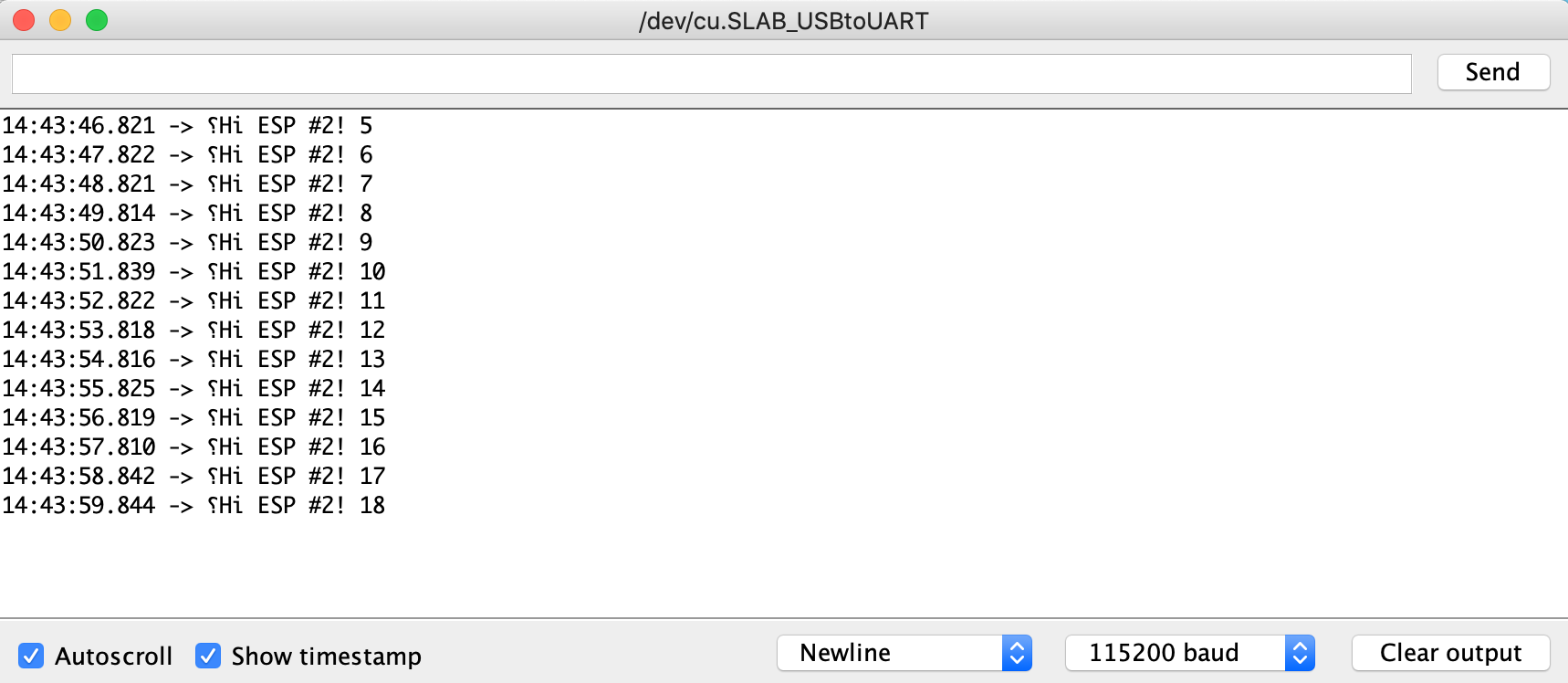
If you are seeing this, that means the UART communication between sender ESP8266 and receiver ESP8266 is working!
Conclusion
Wireless communication is ubiquitous these days and certainly convenient. At the same time it is vulnerable to eavesdroppers and may not be available on every piece of hardware. For this reason, UART makes a valuable addition to your digital tool belt. A large fraction of modern and retro digital devices are capable of UART communication. If you combine that with ESP8266 or ESP32 development boards, you can add WiFi capabilities to devices that weren't built with wireless in mind.
But ESP8266 and ESP32 development boards can do so much more. In addition to being widely used for IoT related projects, they are capable of packet sniffing, handshake capture, and deauth attacks. They can serve basic web pages, hit remote APIs, and create their own WiFi networks. These abilities allow developers and cybersecurity researchers to use them for testing exploits and practicing hacking skills with just a few dollars worth of equipment. They give a fantanstic bang for your buck and can open a lot of doors for your coding, IoT and hacking projects.
For more guides like this one, take a look at our other coding and hacking tutorials